Trevor Horine

Trevor Horine

I am currently a graduate student at Oregon State University working towards a degree in Electrical and Computer Engineering, I graduated in 2022 with my bachelor's degree in electrical and computer engineering with a minor in Computer Science from Oregon State Unversity. My course work is focusing on embedded system design and integrated circuits. I like designing systems that solve interesting problems.

In my free time I enjoy camping, hiking, and rock climbing. In general, I like a good adventure and to explore the outdoors.

Senior Design Tech Demo

Senior Design Tech Demo

In our Senior Design class we were asked to produce a demenstration of a technical skill, for my technical demenstration I designed a minimum viable microcontroller around a chip they specified, the ATMega324P.

My design was implmented using a custom PCB pictured to the right. It has an external crystal, reset button, ICSP programming port, USB for power, and pins for the I/O prots. For this demenstration I had to show that I could take in analog and digital inputs and control digital outputs. To do this I created a voltage divider with a potentometer and a resistor to measure the mid point as an analog signal and wired a button up as an input for my digital input. For a digital output I created a series of 8 LEDs conected to a shift register, this was controlled with the SPI interface on the microcontroller.

Junior Design Final Project

Junior Design Final Project

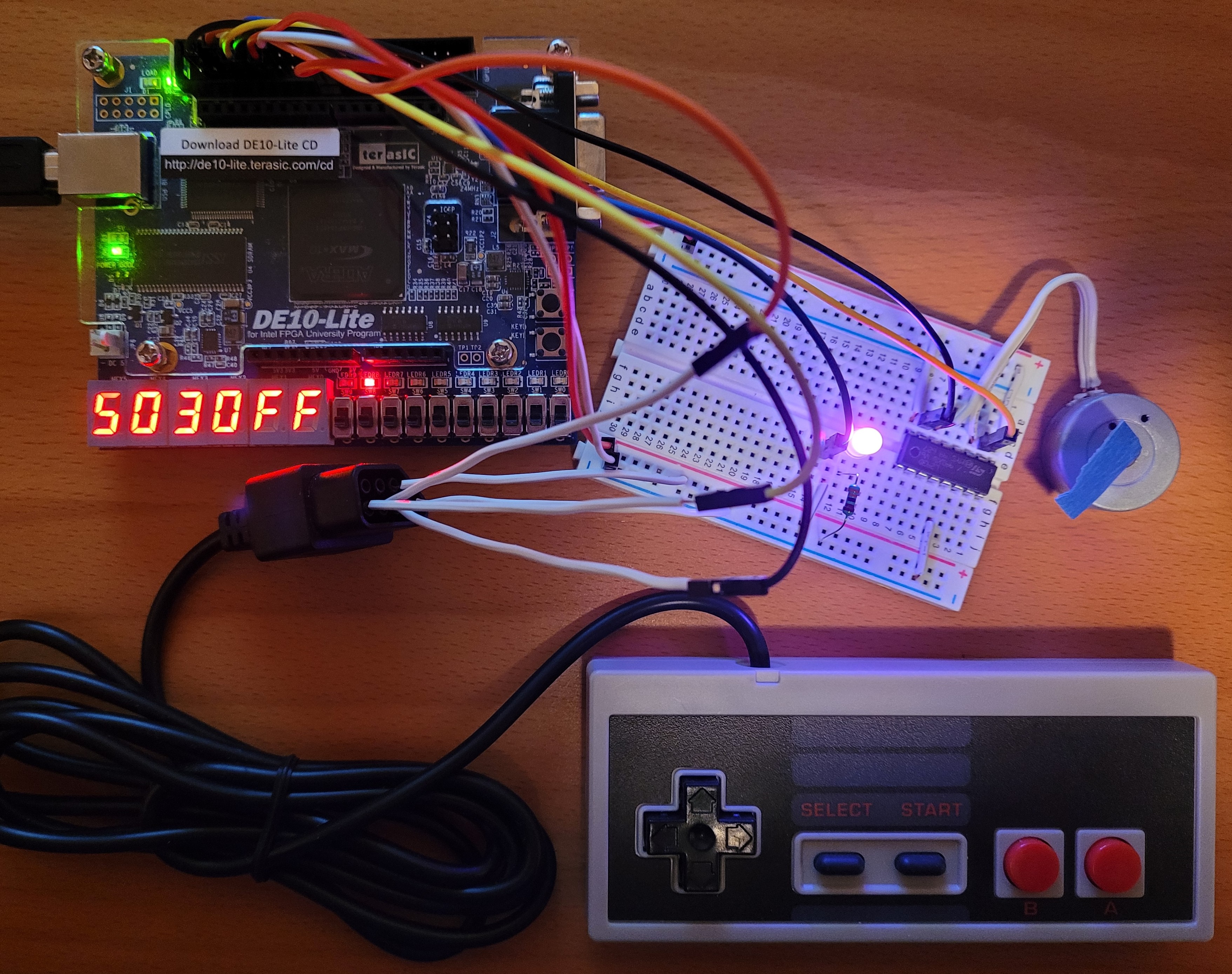
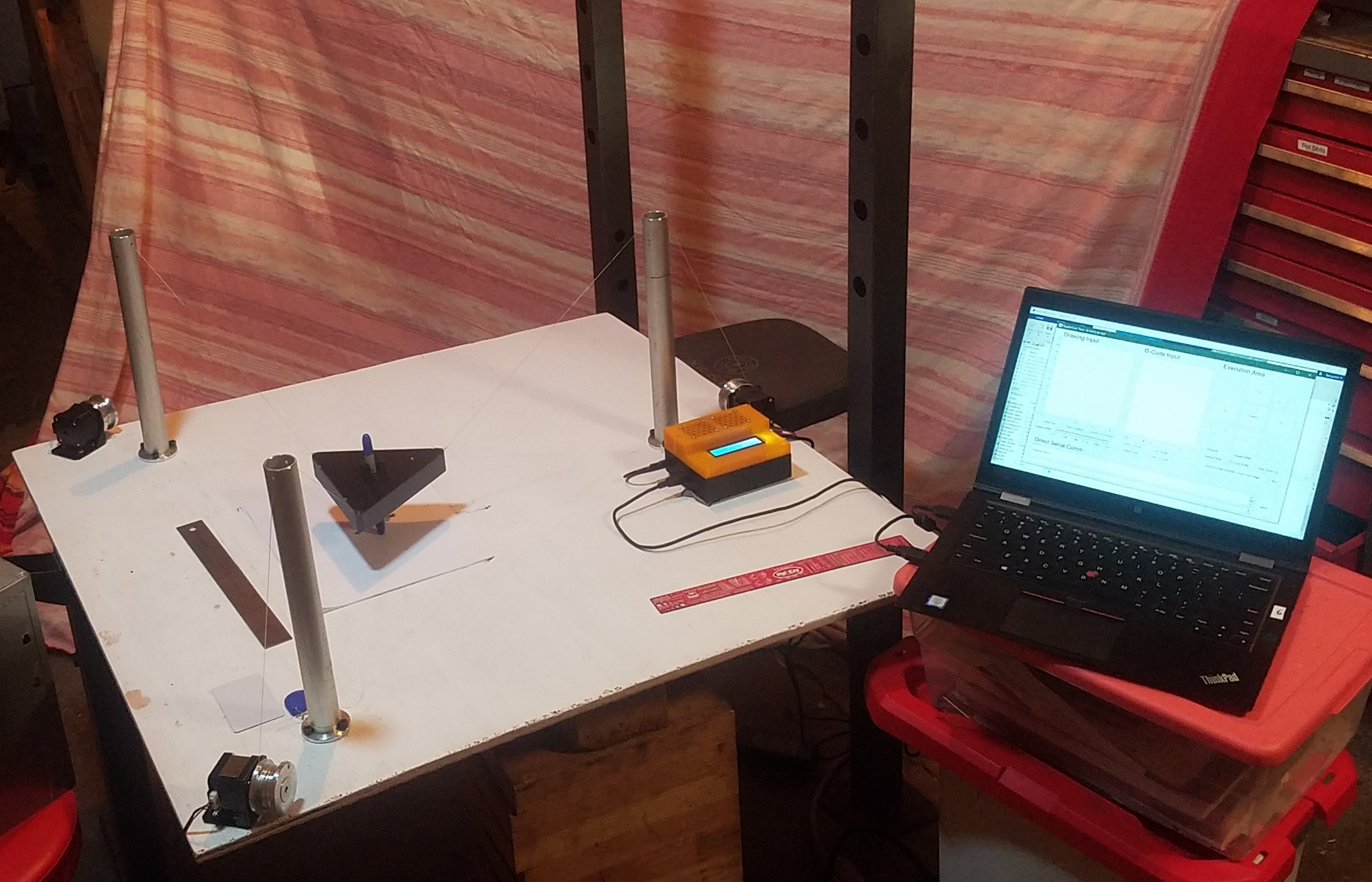
In the second term of Junior Design we worked on term long group projects. In ten weeks, my group designed, built, and tested a SpyderCam style payload positioning device that moves a sensor payload around in an 8.5 by 11-inch area. The sensor payload has a light sensor, RFID sensor and the ability to attach a writing implement. Our system uses three stepper motors to control the length of the strings attached to the payload to move the payload around. The system is controlled with a MATLAB GUI that talks to the Arduino using serial communication.

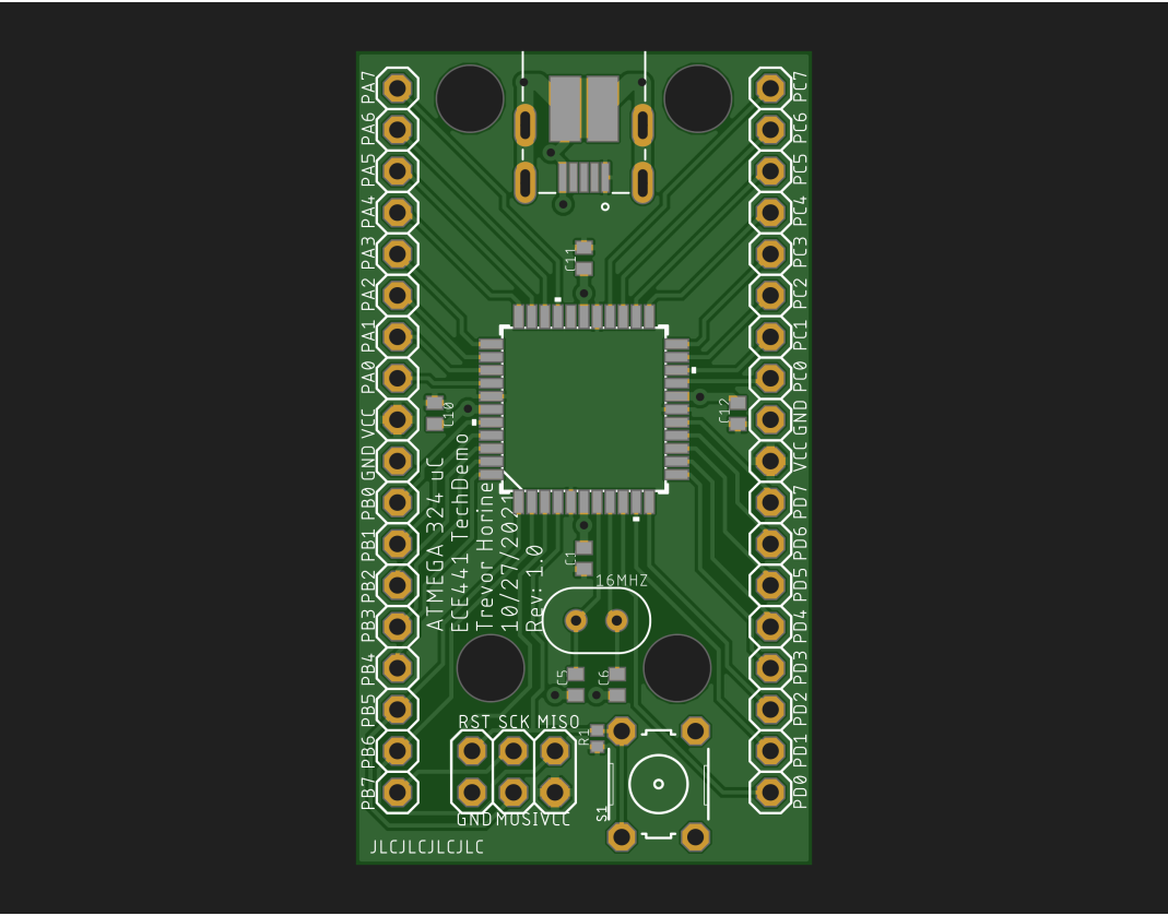
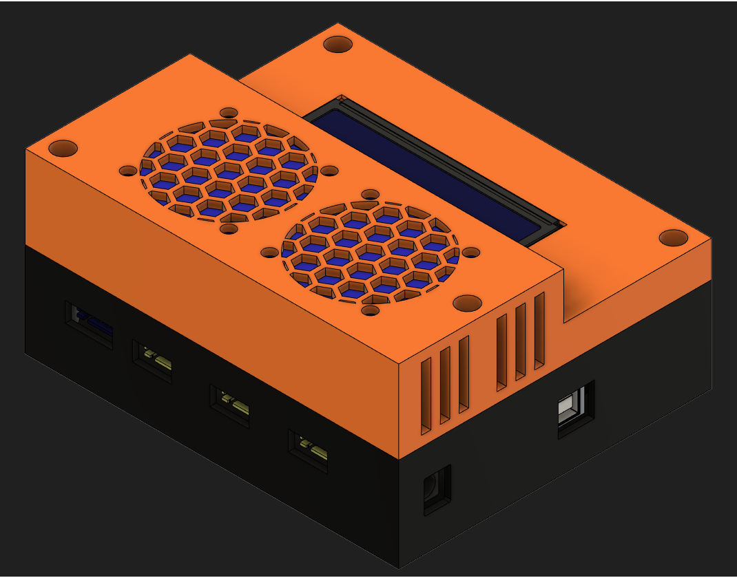
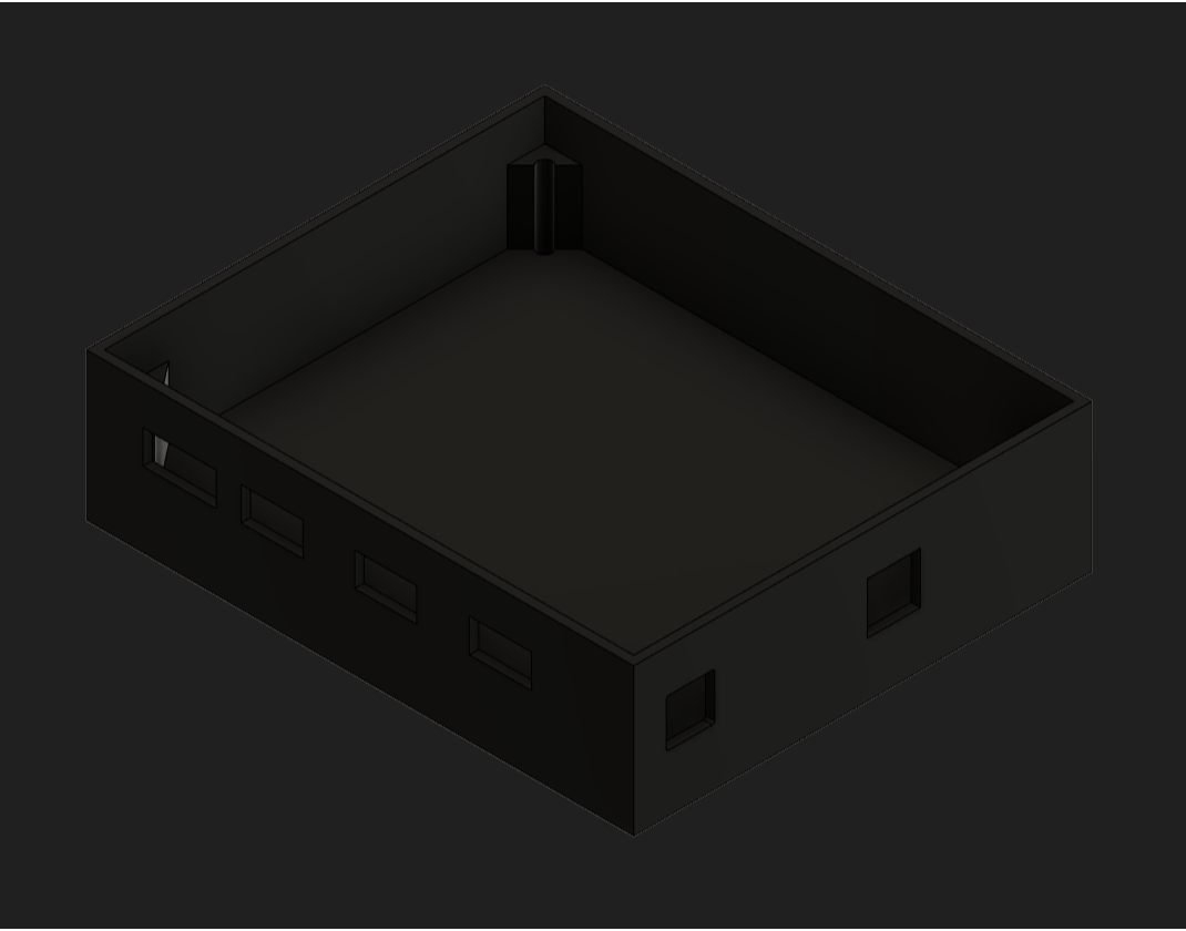
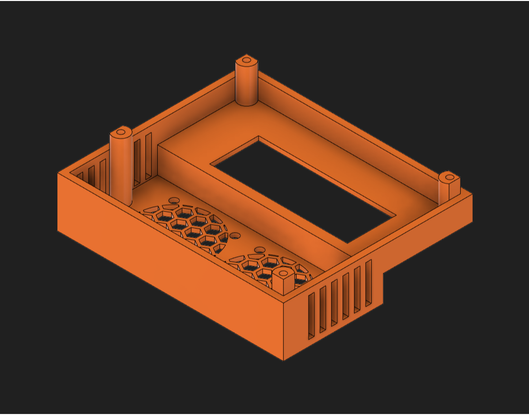
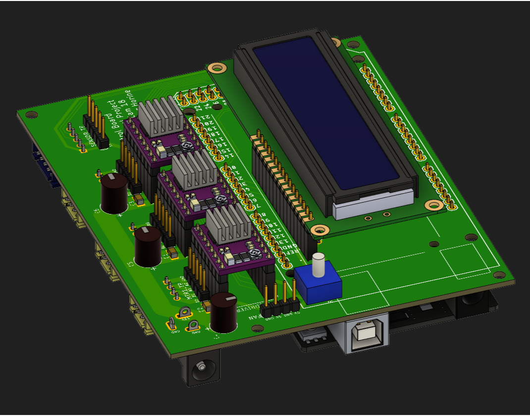
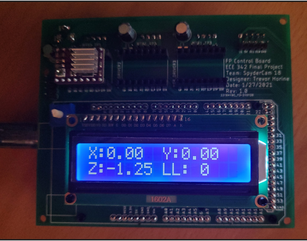
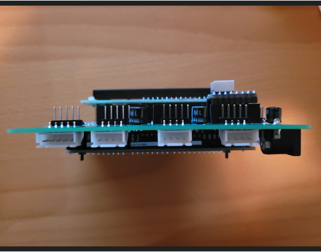
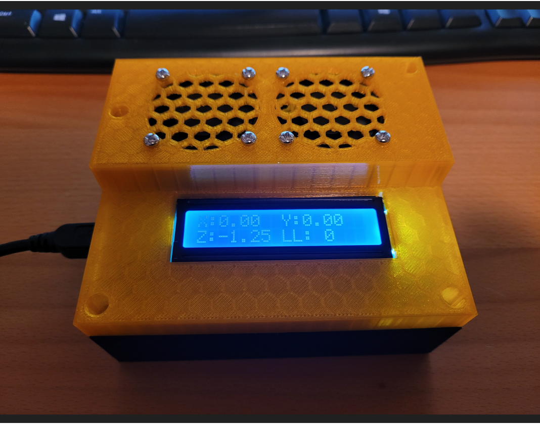
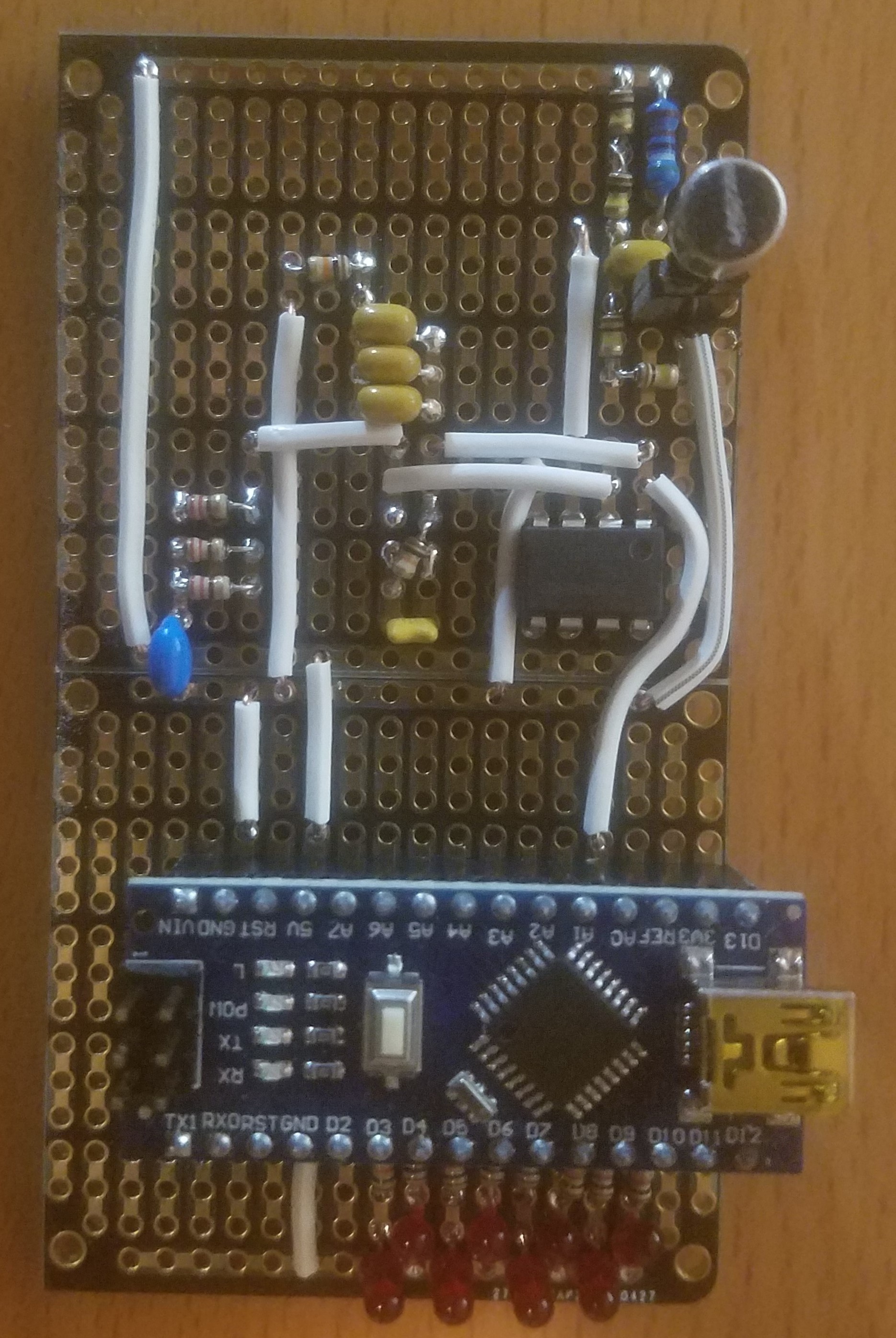
I was responsible for two of the eight blocks that make up the larger system. My blocks were the PCB and the enclosure that it goes in. In order to design the PCB, I first designed the electrical system for our project that would be used to control the motors and collect sensor data. Then I did the layout for the board in EAGLE and sent the boards to the manufacturer. Once I received our boards, I assembled them. The enclosure was created using the 3D model of the PCB that EAGLE created. I used Fusion 360 to design the enclosure around the model of the PCB, once printed the enclosure and PCB were put together and integrated into the larger system.

Junior Design Accelerated Project

Junior Design Accelerated Project

In the first term of my Junior Design class we had a group project to build a frequency detector that would identify frequencies between middle C (261.62 Hz) and high C (523.25 Hz). My group designed an amplifier for the signal created by a microphone and used an Arduino to measure the amplified signal. An Arduino NANO was used and the analog to digital converter (ADC) was configured to sample the signal at around 50,000 times a second. Serial communication was used to pass values to MATLAB where the signal was processed using the built in Fast Fourier Transform (FFT) function in MATLAB. The MATLAB script then passed the highest intensity frequency back to the Arduino using serial communication to light up indicator lights.

Digital Logic Final Project

Digital Logic Final Project

ECE 271 Digital Logic included a final group project that required taking in multiple inputs into the FPGA that we used and using them to drive several different outputs. My part of the project took inputs from an NES controller and output to a DC motor, 7-segment displays, and an addressable RGB LED.

Pressing the right or left sides of the D-pad would spin the motor clockwise or counterclockwise. If the A button and the up button on the D-pad were pressed at the same time it would increment the blue value of the LED, pressing A and the down on the D-pad would decrement the blue value. If the B button was presses in addition to the up or down on the D-pad the red value would be changed, and the start button was used for the green value. The values were also output to the on board seven segment displays in two-digit hexadecimal for each color in the order of red green blue from left to right.